
Introduction
1.75mm LulzBot Adaptor Installation Instructions
Below are instructions to install the 1.75mm LulzBot Adaptor. Please follow these 3 steps carefully and do not hesitate to contact Mosaic at support@mosaicmfg.com if you have any questions throughout the process. Please use caution and ensure that you use proper personal protective equipment during the installation. The user is responsible for any damage caused to any printer or Palette system during the installation and use of this adaptor.
Tools
Parts
-
-
What you will need:
-
1) 1.75mm LulzBot Adaptor (Available Here)
-
Note: Not all parts of the kit will be used for this installation (1x Black PTFE sleeve in Bag B: Titan Aero Extruder Parts, 1x Black Extruder Tube Clip in Bag B: Titan Aero Extruder Parts, 1x Long PTFE Sleeve in Bag B: Titan Aero Extruder Parts)
-
LulzBot Mini 2
-
2 mm and 2.5 mm Allen Key or Hex Screw Driver (Allen Keys provided with printer will work)
-
2 mm and 2.5 mm Allen Key or Hex Screw Driver (Allen Keys provided with printer will work)
-
Personal Protective Equipment (recommended)
-
-
-
Press the provided clip onto the top of the idler arm feeder on the extruder. The clip will snap into place.
-
Ensure that the large round section on the top of the clip is on the left side and aligns with the filament path into the extruder as is shown in the image below. The clip will need to be pressed downward into place and will lock itself. This clip will allow the Palette tube to connect to the extruder easily.
-
-
-
Perform a cold pull to remove any filament from the hot end. It is important to remove all filament from the hot end so that the filament path is evacuated for installation of a sleeve in step 7 below. Wait for the hot end to cool down to below 50 degrees celsius before proceeding in order to avoid injury.
-
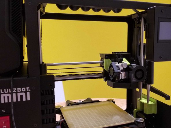
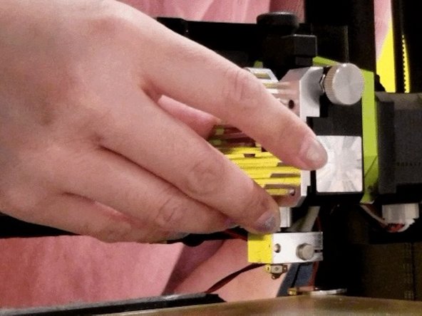
Position the print head on the right side of the printer and about half way up to make it as accessible as possible for the following steps.
-
-
-
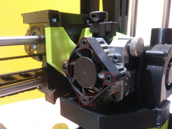
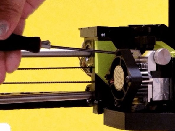
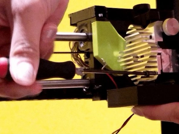
Turn off the printer. Remove 4 screws from the square fan. Gently pull the fan back and allow it to hang from the side. Place the 4 screws in a safe spot as they will be needed for reinstallation shortly.
-
-
-
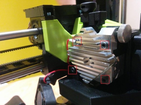
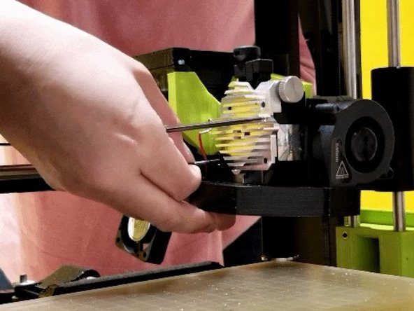
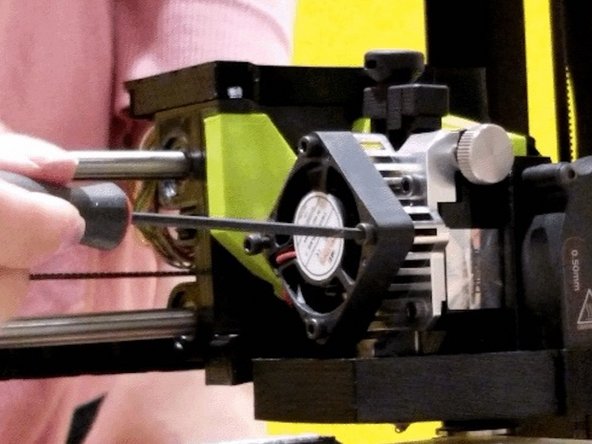
Remove 4 screws from the heat sink.
-
Note: Remember the placement of the shorter screw out of the four. Also, upon unscrewing the last screw on the heat sink, the cooling assembly may drop. Be cautious as the heat sink may come off by itself and the spring from the idler could pop out.
-
Gently separate the heat sink from the motor assembly. Remove the heat sink slowly and cautiously as the idler spring may fall out.
-
-
-
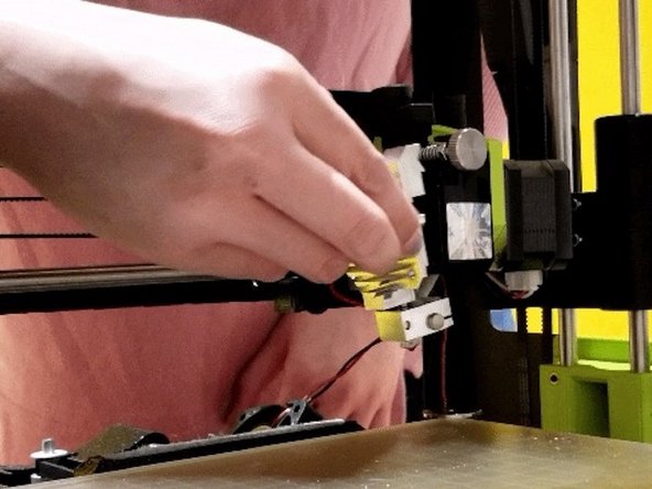
Remove the 2.85mm filament guide that was in the extruder. This part is no longer needed as it will be replaced with a new sleeve provided with the adapter. Keep this somewhere safe in case you want to switch the extruder back for use with 2.85mm filament in the future.
-
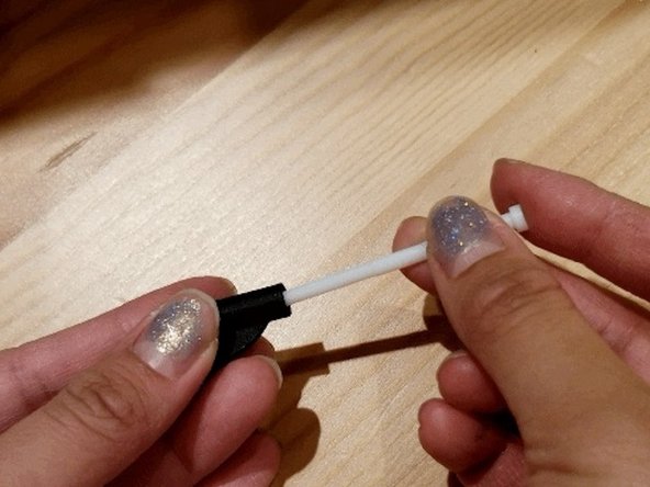
Install the provided tube into the 1.75 mm guide to form this assembly.
-
-
-
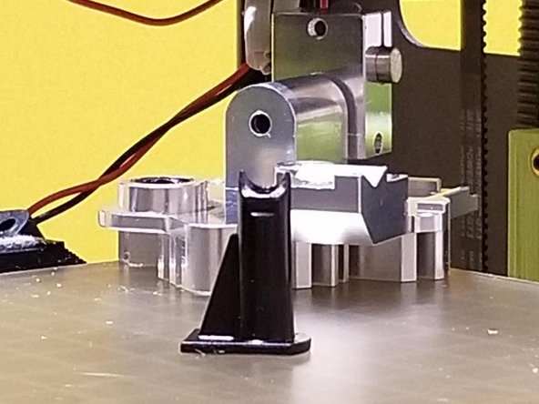
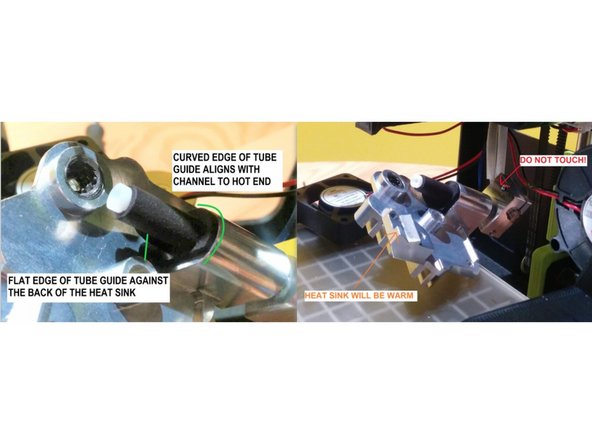
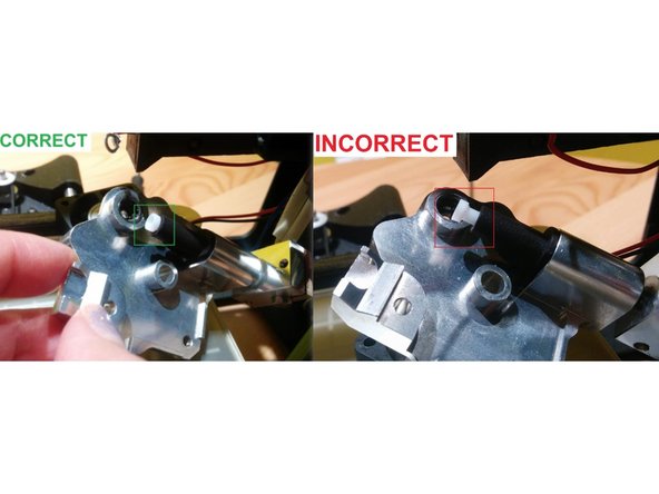
Slide this tube and guide assembly into the hot end until it is all the way into the hot end. The flat side of the guide must align with the inside of the heat sink. When the assembly is properly installed there should be no gap between the upper lip of the tube and the guide, as well as between the guide and the hot end.
-
Ensure that you do not strain the wires connecting the hot end to the print head during this process as excessive force could cause damage.
-
Notes: Please ensure it goes all the way in, like shown in the photos. If the tube is not all the way in, the system will not function properly and it may not be possible to reassemble the system. It is critical that the tube is all the way in.
-
If it does not go in all the way, you may choose to heat up the extruder to 190C and try inserting again.
-
CAUTION: If you choose to heat up the extruder to press the tube in, be careful of the hotend heater block and nozzle as they will be very hot. Only hold the upper portion of the heat sink. You may choose to use protective gloves to avoid the risk of injury.
-
-
-
Allow to the extruder cool before re-assembling.
-
-
-
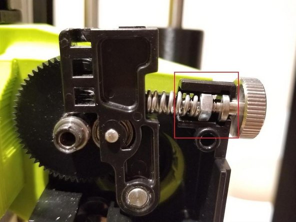
We will now begin reassembling the extruder. Put the idler spring assembly back in place. Ensure the idler spring and thumb screw is in place as shown in the photo below.
-
Reinstall the heat sink. Secure the upper left screw first with the red wire. We found that it is easier to attach the red wire to this screw then to the bottom right screw where it originally was. You can choose to do either.
-
Re-install the cooling fan assembly with bottom left and bottom right bolt of heat sink. Start with bottom-right to secure cooling assembly. Press it upwards against the hot end assembly. Screw in bottom-left to also secure the cooling assembly. Nextscrew top-left with the red wire, using the shortest of the our screws.
-
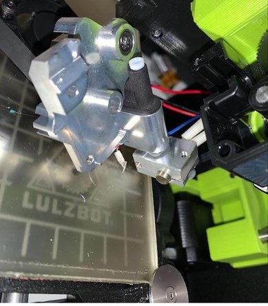
Lastly screw top-right to complete the reinstallation of the heat sink onto the extruder.
-
-
-
Replace Fan.
-
-
-
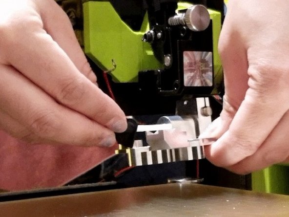
Feed in 1.75mm filament and extruder using the load filament command to make sure there are no blockages and that the kit has been properly installed. Straightening the filament with your finders before loading it into the extruder will help it find the way into the tube You should see filament come out of the nozzle slowly.
-
Please use the LulzBot Workhorse preset profile in CANVAS. You may create an account if needed.
-
Slice this small keychain model or replace it with a model of your choice. It’s important to complete this print to confirm everything is printing well in single color with the adapter before moving onto Palette.
-
-
-
As a bonus step, we have provided bolts and t-nuts (See Bag C: Mounting Hardware from the adaptor) to allow you to attach Palette to your LulzBot Mini 2.
-
This is not required but is highly recommended as it allows for a compact and consistent set-up. This will allow you to use the small sized Palette tube that comes with Palette which will lead to the fastest print start-up time and the best performance.
-
If you would prefer to not mount Palette, it would be recommended that Palette be placed beside the printer with the medium sized Palette tube (see Palette and Printer Setup).
-
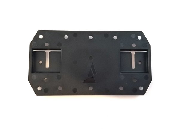
Retrieve the Palette mounting plate from the Palette 2 box.
-
-
-
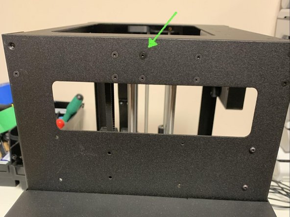
Remove this screw from the left side of the printer.
-
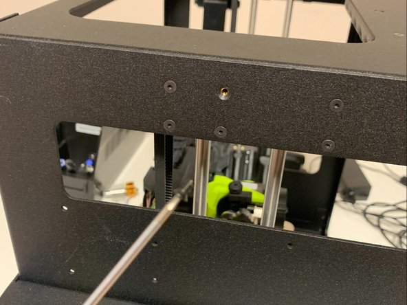
Using the provided longer flat head M3 x 7 mm screw from this adaptor kit, mount the plate to the side of the printer as shown. Tighten the screw ensuring that the plate is level.
-
-
-
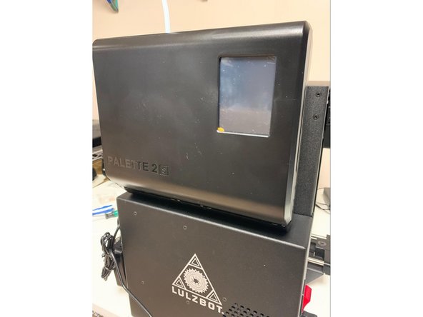
Slide Palette onto the mount and ensure that it is secure before allowing it to stay on its own. The bottom of Palette will rest on the top of the electronics enclosure on the side of the printer. Be cautious when working with Palette or when moving the printer while Palette is installed as Palette will separate from the printer if lifted upwards.
-
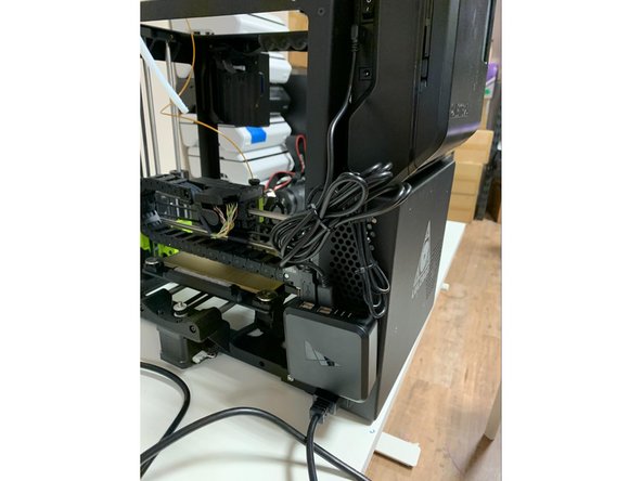
Follow the instructions provided in the manual with the Canvas Hub. It is recommended to mount the Canvas Hub using the provided velcro tabs to the back of the printer so that it is out of the way of the filament. It is also recommended to bundle the wires above the Canvas Hub to ensure that they are tidy and out of the way of any moving parts.
-

If you have any questions, please contact us at support@mosaicmfg.com.
If you have any questions, please contact us at support@mosaicmfg.com.
