
Introduction
If you want to use Palette with a LulzBot (TAZ 4, TAZ 5, TAZ 6, Mini), this article is for you! We've prepared a small kit for LulzBot owners to use 1.75 mm filament.
Disclaimer: This tutorial is a "use at your own risk" type of thing. LulzBot doesn't really recommend using 1.75mm filament on their machines, but we have a TAZ 5 working very well with the modification outlined here. While modifications made to LulzBot printers that are currently under warranty may void warranty coverage for the modified components, the 1.75mm conversion is reversible if completed properly and should not affect the performance of 3mm printing if reversed. Questions related to LulzBot warranty coverage should be addressed to support@lulzbot.com prior to making any modifications. This modification involves installing PTFE tubing into the hot end. To stay within PTFE's safe range, with this mod, one should keep the extruder temperature at ≤ ~230C.
What are the benefits of using 1.75mm filament?
Adafruit's Ruiz brothers (Noe & Pedro) and Hackaday's Brian Benchoff discuss some of the benefits of 1.75mm filament in these two articles on Adafruit and Hackaday. Neotko also discusses advantages here.
Some people have converted to 1.75 because:
- "... mainly wanted to avoid the classic ‘dripping’ from 2.85 machines and the need for [high temperatures] to print [quickly]..."
- "... 1.75mm allows [me] to have a shorter hotzone... so there’s less hot material at any given time, [which] allows me to have [better] precision when [printing] small texts..."
- exotic filament availability
- better options for flexible filaments
- reduced force required for extrusion (which decreases likelihood of grinding issues)
- compatibility with Palette+!
Before getting started
For the TAZ 5, TAZ 6, and Mini, please print this file with at least 30% infill density (the part will need to be durable). (You will need this part for step 2.)
Tools
Parts
No parts specified.
-
-
What you will need:
-
The hex keys ("Allen keys") that came with your printer.
-
The 1.75 mm LulzBot conversion kitfrom Mosaic. It includes: Upper PTFE sleeve (the shorter one), Lower PTFE sleeve (the longer one), 4mm Deburring Bit
-
Note: no drill is required.
-
-
-
The best way to do this is to perform a cold pull:
-
Heat your extruder to the extrusion temperature of the filament that you last used.
-
Turn off the heater. Unlatch the idler bearing so that the filament can be pulled out manually (later).
-
Wait for the temperature on the screen to reach about 150-160°C if the last used filament was PLA, or 200-210°C if you were using ABS.
-
Once the nozzle reaches this temperature, quickly pull the filament out of your nozzle.
-
You should see a filament come out that has a bulb at the end. It should look like this.
-
-
-
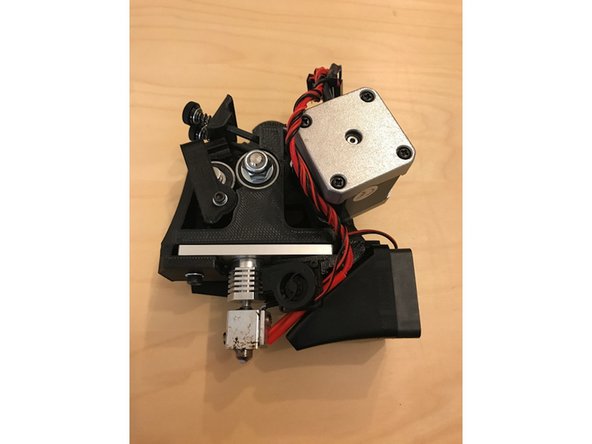
Start by removing the extruder from your printer so we can handle it more easily. Turn off your printer, unplug it from a power source, and ensure the extruder has fully cooled down.
-
To remove the LulzBot Mini's extruder, please follow LulzBot's instructions to remove the extruder here.
-
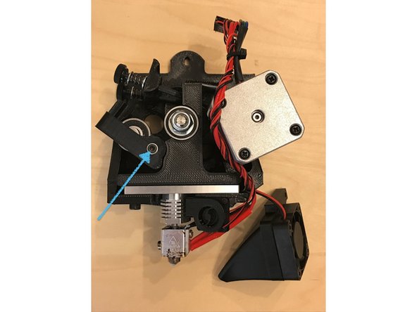
For the TAZ 5 and TAZ 6, start by removing the bolt that secures it to the carriage.
-
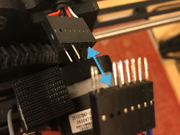
Unplug the cable connector.
-
Remove the extruder assembly from the carriage.
-
-
-
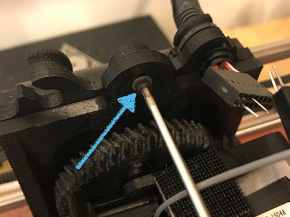
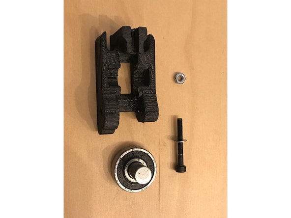
Now that the extruder has been removed, use a hex key (Allen key) to remove the bolt that secures the idler arm to the extruder assembly.
-
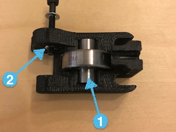
Slide the idler assembly out of the extruder assembly, and remove the idler bearing (1) and nut (2) from the 3D printed structure.
-
Now that you've separated the parts, reinstall the idler bearing and nut into the new 3D printed structure you printed.
-
Reinstall this new idler assembly back onto the extruder assembly.
-
-
-
Remove the hot end from the extruder assembly so that we can install a PTFE sleeve. This helps constrain the 1.75 mm filament.
-
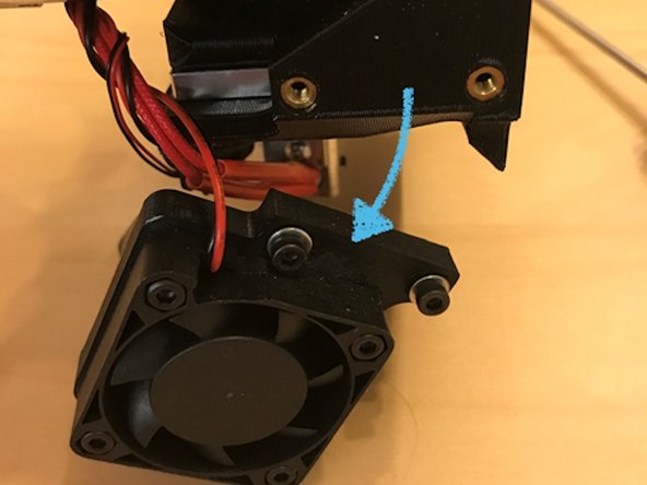
Start by removing the fan from the side of the extruder assembly. This will help us access other bolts.
-
Then, using a hex key (Allen key), remove the bolts from the fan.
-
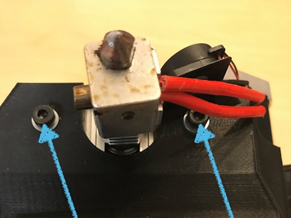
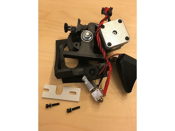
remove the two larger bolts on the bottom of the extruder assembly, and disassemble the hot end from the 3D printed structure.
-
Be careful not to disturb the delicate wiring near these bolts.
-
-
-
Locate the filament channel in the 3D printed extruder housing, and try to press the upper PTFE sleeve into the channel with the tapered side first. Note the groove in the PTFE tube. Do not apply too much force when trying to insert the PTFE tube. If you run into issues with inserting the PTFE tube, see the following steps.
-
-
-
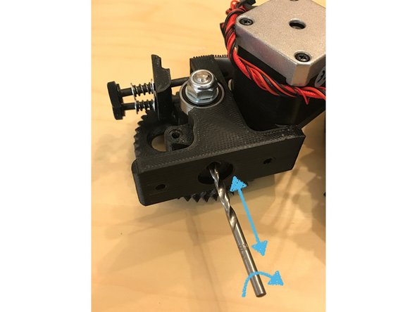
If the PTFE tube cannot easily enter the filament channel, then we may need to expand the inside of the channel (carefully!). The channel should be 4 mm, but sometimes burrs and printing imperfections make the channel's diameter slightly less than 4 mm. The conversion kit includes a 4 mm deburring bit to help solve this problem.
-
Note: a drill should NOT be required to perform this deburring process. If the PTFE tube does not fit easily into the channel, gently pass the deburring bit into the channel and use your fingers to rotate the bit. Do not to press the bit into the channel too far, or it may damage your metal drive gear.
-
After rotating the bit, try to install the PTFE tube again. Repeat the process until you can press the PTFE tube in without using excessive force.
-
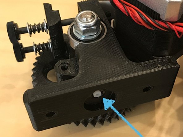
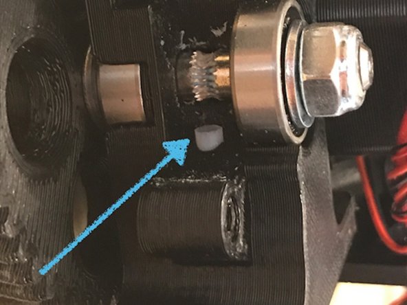
The sleeve should be pressed in until the bottom is flush with the bottom of the filament path channel. You will see the PTFE emerge below the hobbed gear.
-
-
-
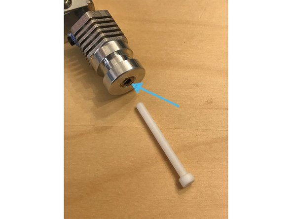
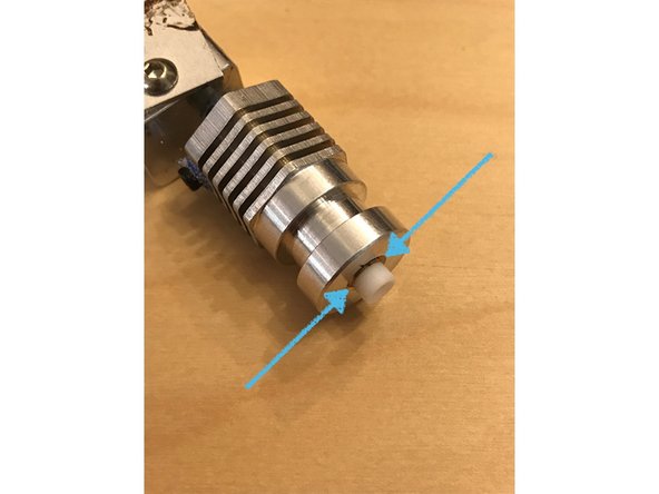
Start by locating the inlet to the hot end.
-
Push the lower PTFE sleeve into the hot end and ensure that the top cap of the PTFE sleeve makes direct contact with the top of the hot end.
-
If the PTFE sleeve cannot be pressed far enough into the hot end for the top cap to make proper contact, there is likely some filament still inside the hot end that was not successfully removed during the cold pull in Step 1.
-
In order to remove this filament from the hot end, you can either (1) repeat the cold pull, or (2) you can heat up the hot end and use the PTFE tube gently to press the melted material down, into, and through the hot end's nozzle.
-
Please exercise caution of you are heating up your hot end during this step. Use proper personal protective equipment and be weary of fire hazards.
-
-
-
Reassemble the extruder assembly by following the disassembly instructions in reverse order.
-
Install the assembly back onto the printer carriage, and reconnect the cables.
-
Turn on your printer, heat the extruder, and load in some 1.75mm filament. (We recommend starting with PLA at around 210°C.)
-
Using the movement menu, load 10 to 20cm of filament through the extruder to test its performance.
-
Tune the idler spring tension accordingly.
-
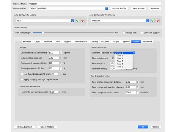
In your slicer, change the filament diameter from 2.85/3mm to 1.75mm, and try a test print! If you're using Simplify3D, please make sure to change the filament diameters for all the toolheads, not just for Tool 0.
-
There are additional tips on printing with 1.75 mm filament on your LulzBot here.
-


If you have any questions, please contact us at support@mosaicmfg.com.
If you have any questions, please contact us at support@mosaicmfg.com.
Cancel: I did not complete this guide.
One other person completed this guide.

2 Comments
The 1.75 mm LulzBot conversion kit from Mosaic that you have linked here appears to come with a 5-pack of part B, what about part A? The purchase listing makes it unclear whether this actually includes all the necessary parts for the mod.
Apologies as the link is incorrect, this leads to the P3 Splice Tubes. We are currently out of the LulzBot adapter kits.